

What Is The Working Principle of Line Isolator?
Views: 0 Author: Site Editor Publish Time: 2026-07-31 Origin: Site


Specifying the wrong isolation component leads to catastrophic failures in any electrical infrastructure. It can cause severe equipment damage almost instantly. You might face serious safety compliance violations during a routine inspection. Sometimes, it simply ruins your sensitive data by severely degrading signal integrity. Engineers must get this critical choice right. The term "line isolator" often causes confusion because it describes two very distinct technologies across different industries. In high-voltage power grids, it refers to heavy-duty mechanical switches. In radio frequency (RF) and signal processing, it points to precision galvanic isolation devices. Both applications share a fundamental goal. They interrupt a specific electrical path to protect vital systems. We will explore exactly how these devices function. This guide bridges the gap between basic electrical theory and pragmatic engineering. You will learn how core principles dictate component selection. We will evaluate system reliability and strict safety standards. Our technical breakdown helps you make smart procurement decisions safely.
Key Takeaways
The core working principle relies on physical disconnection (power applications) or galvanic/magnetic isolation (signal applications) to block DC currents and ground loops.
Selecting an in-line isolator requires balancing isolation voltage requirements against acceptable insertion loss.
Compliance with industry standards (IEC/IEEE) is the primary baseline for evaluating manufacturer claims and ensuring operational safety.
Proper implementation requires analyzing the specific environment—from substation weather conditions to RF system impedance matching.
The Core Working Principle: Breaking the Conductive Path
The Physics of Isolation
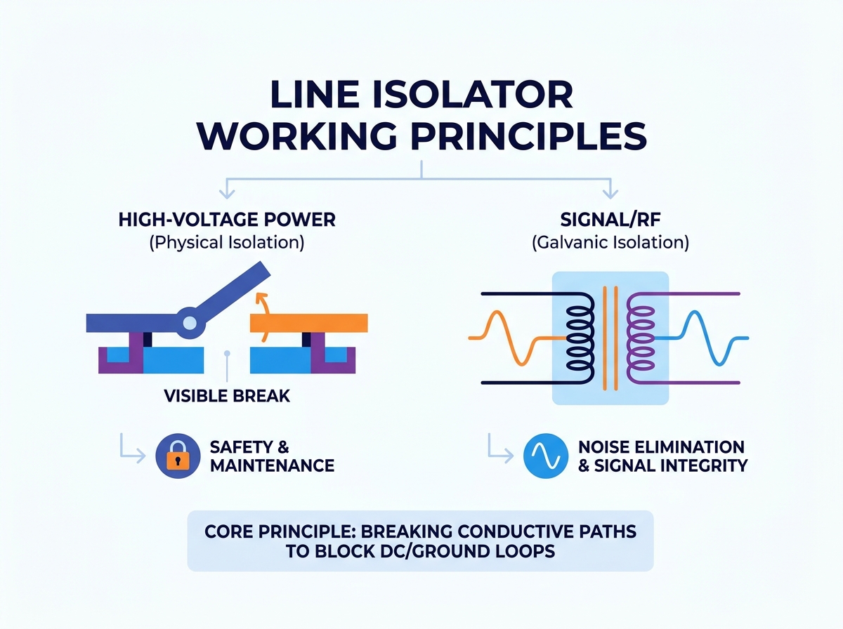
Electrical isolation fundamentally stops unwanted current flow. It interrupts circuit continuity securely. Desired operations continue seamlessly across the barrier. You create a controlled roadblock. This roadblock stops fatal faults. Energy takes many forms. We must manage this energy precisely. Physical separation stops high voltages. Magnetic flux transfers data across gaps. The physics remains simple but powerful. You must sever the direct conductive path. This single action prevents catastrophic energy transfer between connected systems.
High-Voltage Context (Physical Isolation)
Power systems require absolute physical isolation. You use mechanical switches to achieve this. Operators perform no-load switching operations. This means you only open the switch when no current flows. The isolator physically separates massive circuits. You get 100% de-energization every time. Maintenance crews rely entirely on this visible break principle. They can see the actual physical gap in the air. This guarantees human safety during grid repairs. Air becomes the dielectric insulator. The gap must withstand lightning strikes. It must hold back extreme voltage surges safely.
Signal and RF Context (Galvanic Isolation)
Signal applications require a totally different approach. You cannot simply cut a communication wire. Data must still flow continuously. An In-line Isolator provides this necessary galvanic isolation. It uses audio transformers, precise optocouplers, or capacitive coupling techniques. These methods pass alternating current (AC) signals across a barrier seamlessly. They block direct current (DC) voltages completely. This blocking action eliminates destructive ground loop interference. Unwanted electrical noise disappears instantly. Your clean signals survive the crossing. Your sensitive receiving electronics stay perfectly safe.
The "Biggest Effect"
What is the primary outcome of these principles? We must look at the direct results. In power distribution systems, it guarantees absolute human safety. A worker trusts their life to that air gap. In signal setups, it ensures noise elimination. It blocks dangerous voltage surges from data lines. You secure clean, error-free data transfer. These effects justify the initial engineering investment. Understanding this ultimate purpose guides every procurement step. It sets the baseline for evaluating return on investment.
Solution Categories: Aligning the Principle with Your Application
Substation and Grid Isolators
Different environments require specific mechanical layouts. Let us examine high-voltage grid hardware. Center-break isolators pivot right in the middle. They suit areas lacking vertical space. Double-break versions open at two distinct points. They handle much higher voltages securely. Pantograph isolators extend vertically to connect overhead lines. You find them in modern railway power systems. You use these specific devices for high-voltage maintenance. They route immense power across complex grids safely. They isolate massive transformers for routine oil testing.
RF and Audio In-line Isolators
Data protection demands smaller, precise components. Coaxial devices protect amateur radio receivers. They block static buildup on long antennas. Audio ground loop isolators clean up professional sound systems. You use them to protect sensitive audio interfaces. They maximize your critical signal-to-noise ratio. They prevent expensive equipment damage from sudden static discharge. Broadcast engineers deploy them constantly. They stop hums and buzzes in live television feeds. Medical equipment uses similar components to protect patients from stray currents.
Decision Matrix
How do you choose the right category? I prepared a logical framework below. It connects your working environment directly to the required isolator category. Review your primary system constraint first. Then, select the appropriate matching technology.
Isolator Application Matrix
Application Environment | Primary Engineering Goal | Required Isolator Category | Typical Operating Mechanism |
|---|---|---|---|
High-Voltage Substation | Human safety during maintenance | Double-break mechanical isolator | Motorized or manual lever |
Railway Overhead Lines | Routing power in tight spaces | Pantograph isolator | Motorized linkage |
Broadcasting Studio | Audio ground loop elimination | Audio isolation transformer | Passive magnetic induction |
Radio Frequency Tower | Static discharge protection | Coaxial line isolator | Capacitive or inductive coupling |
Key Evaluation Criteria for Procurement and Specifying
Voltage and Current Ratings
You must assess the maximum operating voltage carefully. Look closely at the short-time withstand current (STC) rating. Do not over-specify these values blindly. Over-specifying inflates project costs unnecessarily. Match the ratings exactly to your operational peak levels. Consider emergency overload conditions. The device must survive a temporary fault current until the breaker trips. If you under-specify the STC, the mechanical contacts will melt together. This destroys the equipment entirely. Engineers must balance safety margins against budget realities.
Insertion Loss and Bandwidth
Data transmission always involves a technical trade-off. An In-line Isolator absorbs some signal energy. You lose a fraction of your signal strength. We call this insertion loss. You must evaluate manufacturer data sheets rigorously. Balance signal degradation against overall isolation efficacy. High frequencies often suffer much more loss. Pay strict attention to the usable bandwidth. A device rated for audio frequencies will destroy a high-speed digital signal. Measure your acceptable decibel loss limits before ordering.
Mechanical Endurance and Environmental Resilience
Build quality matters immensely for longevity. Check the corrosion resistance of all exposed metal parts. Evaluate expected contact wear over time. Devices must perform flawlessly in extreme temperatures. Substation switches face freezing rain and blistering sun. They must survive high-vibration industrial environments. Look for ruggedized, weather-sealed housings. Silver-plated contacts offer superior conductivity. They resist performance-degrading oxidation better than bare copper. Consider the effects of coastal salt spray if applicable. Mechanical resilience prevents premature component failure.
Compliance and Authoritative Standards
Independent verification remains completely non-negotiable. Power network components must follow strict IEC 62271 guidelines. Signal devices require exact FCC or CE benchmarks. Never trust vague marketing claims from unknown suppliers. Reject vendors lacking verifiable third-party testing reports. Adherence to known standards serves as your primary trust indicator. IEEE frameworks provide excellent testing methodologies. Request the actual lab certificates. Check the testing dates for relevance. Certified equipment protects your liability. It ensures uniform performance across your entire network.
Implementation Realities and Common Adoption Risks
The "Load Switching" Hazard
Power devices carry extreme operational risks. A mechanical isolator must never open under active load. It lacks internal arc-extinguishing mechanisms. Circuit breakers handle load switching safely. Isolators strictly provide offline separation. Opening an energized mechanical switch causes deadly electrical arcs. The plasma arc can jump across phases. It destroys the substation instantly. You must install robust mechanical interlocks. These interlocks prevent catastrophic human errors. They physically block the operating handle until the main breaker trips open.
Impedance Mismatches
Signal setups have their own complex pitfalls. Improper component selection causes serious technical issues. An unmatched line isolator creates standing wave ratio (SWR) spikes. The signal energy reflects back to the source transmitter. This ruins transmitter efficiency quickly. High SWR generates extreme heat in the final amplifier stages. It eventually cooks expensive radio equipment. Always verify your specific system impedance before installation. Match 50-ohm systems strictly to 50-ohm components. Measure the system sweep after final installation.
Maintenance Overhead
You must plan accurately for continuous upkeep. Motorized operating mechanisms fail differently than manual ones. Motors burn out or lose lubrication. Contacts degrade steadily over time. Surface oxidation increases dangerous electrical resistance. High resistance causes localized heating. Make transparent assumptions about your lifecycle needs. Schedule routine visual inspections. Clean the contacts during planned outages. Apply approved conductive greases. Neglected isolators often jam closed. This forces unplanned, expensive network shutdowns for emergency repairs.
Cost vs. Capability
Avoid cheap alternatives completely. Uncertified products look tempting on a procurement spreadsheet. However, they compromise system-wide safety daily. They introduce hidden vulnerabilities into critical infrastructure. A failed isolation barrier destroys expensive downstream electronics. It exposes operators to lethal voltages. Cheap plastics turn brittle under UV exposure. Cheap metals corrode rapidly in damp environments. Invest your budget in proven reliability. Quality components deliver decades of trouble-free operation. They protect your much larger capital investments effectively.
Shortlisting Logic: How to Choose the Right Line Isolator
Step 1: Define the Absolute Constraints
Let us break down the selection process systematically. You must follow these structured steps closely.
Identify the exact operating environment carefully. Note extreme temperatures, humidity, and pollution levels.
Measure your strict spatial limitations for physical installation. Ensure adequate clearance for mechanical movement.
Determine your primary engineering goal. Are you ensuring human safety or data signal clarity?
These constraints filter out incorrect technologies immediately. You narrow your focus to workable solutions only.
Step 2: Establish the Technical Baseline
Determine the exact required isolation voltage strictly. Define acceptable insertion loss metrics for your data stream. Choose the correct connector types for signal applications. Ensure perfect mechanical compatibility for power setups. Match your system impedance precisely. Calculate your necessary short-time withstand current. Document all these figures clearly. This creates your non-negotiable technical baseline. Any product failing these numbers gets rejected instantly.
Step 3: Vet the Manufacturer
Assess overall vendor credibility thoroughly. Read their proposed warranty terms in detail. Confirm the guaranteed availability of spare replacement parts. Test their technical support responsiveness early. A good vendor answers complex engineering questions quickly. Look for companies holding ISO 9001 certifications. Ask for references from similar industrial sectors. Solid manufacturers stand behind their field performance. They publish comprehensive engineering data transparently.
Next-Step Action
Draft a highly comprehensive Request for Quote (RFQ). Demand specific performance data from your shortlisted suppliers. Ask for independent test reports specifically. Request thermal performance curves. Do not accept generic, abbreviated specification sheets. Make the vendors prove their compliance. Compare their technical submissions side-by-side. Make your final decision based on verified engineering facts, not aggressive sales pitches.
Conclusion
Let us review our primary findings. Understanding the basic physics of isolation is only your first step. You must align that working principle with harsh environmental realities. Strict compliance with industry standards ensures a successful, safe procurement decision. We highlighted the fatal dangers of mistaken load switching. We explored how galvanic barriers protect sensitive signal equipment. Action represents your logical next move. Gather your precise system metrics immediately. Encourage your purchasing team to consult an internal engineering specialist. Reach out to a certified technical sales representative today. Validate your exact specifications before finalizing any major purchase. Proper selection guarantees safety, reliability, and excellent long-term performance.
FAQ
Q: What is the biggest effect of a line isolator in a system?
A: The primary outcome depends completely on the application. In high-voltage power networks, it guarantees absolute human safety by creating a visible physical break for maintenance workers. In signal systems, it eliminates destructive ground loops and blocks DC noise, ensuring clean data transmission.
Q: Can an in-line isolator act as a surge protector?
A: They serve different core functions. An isolator blocks DC voltage and breaks ground loops constantly. A surge protector actively clamps sudden transient voltage spikes. While galvanic isolation blocks some surges naturally, you still need dedicated surge suppression devices for comprehensive lightning and transient protection.
Q: Why can't a line isolator be used to interrupt fault currents?
A: Mechanical isolators lack internal arc-extinguishing mediums. Circuit breakers contain special gas or vacuum chambers to snuff out electrical fires during load interruptions. Opening an isolator under active fault current creates a massive, deadly electrical arc that destroys the equipment instantly.
Q: How does a ground loop isolator actually remove noise?
A: It uses galvanic isolation, typically through an internal audio transformer. The transformer passes the desired AC audio signal magnetically between two separate coils. It completely blocks the unintended DC path connecting the two devices. This physical separation instantly stops the humming noise caused by ground voltage differences.


