

What Degree of Depolarization Should You Specify?
Views: 0 Author: Site Editor Publish Time: 2026-09-28 Origin: Site


Managing Polarization-Dependent Loss and signal fading is a constant struggle for optical engineers pushing the limits of high-performance networks. Converting polarized light into an effectively unpolarized state is critical to maintaining system integrity. Finding that exact specification sweet spot is notoriously challenging. Over-specifying drains your budget and inflates module size. Under-specifying invites catastrophic system failures and data loss. How do you determine the precise degree of depolarization your architecture demands? How do you select the right component for the job? Let us dive into the engineering realities of polarization management.
Core Metrics of Polarization Management
Terminology Matters: Optical engineers typically specify a maximum Degree of Polarization. A lower percentage indicates a higher degree of depolarization and a significantly more effective component.
Application is King: Different infrastructures have vastly different requirements. Raman amplifiers, fiber optic gyroscopes, and optical measurement tools require highly specific benchmarks to function correctly without over-engineering the system.
System Synergy: Polarization management devices do not operate in isolation. They achieve optimal phase stability when correctly paired with other components, such as a specialized isolator or a Faraday mirror.
Cost Versus Performance: Specifying an unnecessarily high degree of depolarization can drastically increase component costs and physical footprint. Understanding the specific coherence length of your light source is the key to finding the optimal specification balance.
Redefining Degree of Polarization Versus Depolarization
To specify the correct optical components for your network or sensor array, you must establish a rigorous understanding of the underlying physics governing polarization states.
Defining the Terms Without the Jargon
In optical engineering, the Degree of Polarization is a quantitative metric describing the proportion of an electromagnetic wave that is polarized. Mathematically, it is defined as the ratio of the polarized optical power to the total optical power of the light beam. When expressed as a percentage, a value of 100 percent means the light is completely polarized. Conversely, zero percent indicates completely unpolarized light.
The term depolarization refers to the deliberate process of converting polarized light into an effectively unpolarized state. Therefore, a strict inverse relationship exists between the effectiveness of the component and the resulting residual polarization. When procurement managers or engineers demand a high degree of depolarization, they are actually targeting a very low residual metric. Achieving a residual value of less than one percent means the device has successfully randomized almost all the polarization states of the incoming light.
Why We Need Unpolarized Light in Fiber Optics
Imagine a long-haul telecom link where standard single-mode fiber twists and bends through underground conduits. In such high-performance environments, maintaining a single state of polarization over long distances is physically impossible due to environmental stressors and temperature fluctuations. When polarized light travels through standard fiber, it splits into two orthogonal polarization modes that travel at slightly different speeds. This phenomenon, known as Polarization Mode Dispersion, causes pulse broadening and severe signal degradation in high-speed telecommunications.
Furthermore, active components like optical amplifiers exhibit Polarization-Dependent Gain. In a Raman amplifier setup, the gain relies heavily on the relative polarization states of the pump laser and the signal. If the pump light remains highly polarized, amplification will fluctuate wildly as the signal drifts along the fiber. Passing the pump light through a depolarizing unit averages out the gain across all polarization states, effectively mitigating signal fading and ensuring consistent amplification across the entire network.
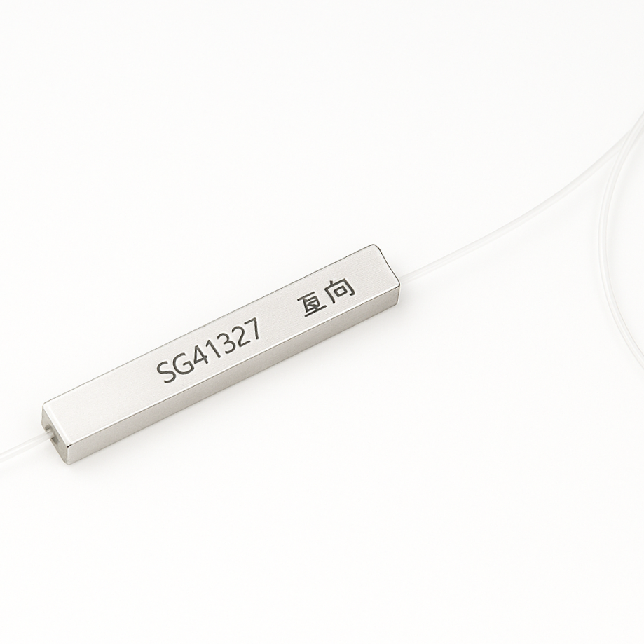
Industry Trends Driving Optical Specifications
Recent market analyses highlight a massive shift toward Co-Packaged Optics and ultra-dense transceiver modules. As data centers push for 800G and 1.6T architectures, the spatial footprint of every passive component is under intense scrutiny. The industry heavily favors precision-matched delay lengths that achieve target specifications within millimeter-scale constraints. We are rapidly moving away from brute-force methods that rely on bulky fiber spools. Understanding the precise physics of your light source is now mandatory for modern optical integration, ensuring components fit into tight spaces without sacrificing optical performance.
The Engineering Balancing Act of Cost and Performance
From a Bottom-of-Funnel perspective, selecting the correct specification is a critical balancing act. Engineers must weigh technical performance against the Bill of Materials cost, physical footprint, and supply chain lead times.
The Risks of Under-Specifying
Accepting a higher residual polarization than your architecture can tolerate introduces severe operational risks. In optical sensor systems, residual polarization leads directly to phase errors. These phase errors translate into measurement drift, fundamentally compromising the navigational accuracy of sensitive gyroscopes.
In telecommunications, an inadequate specification for a Raman pump laser leads to highly unstable gain profiles. If the residual polarization remains above ten percent, the infrastructure will experience significant instability. This causes signal fading, elevated Bit Error Rates, and ultimately, dropped data packets. For research technicians characterizing passive optical components in a lab setting, an inadequate setup will yield inconsistent insertion loss measurements, invalidating weeks of critical quality control data.
The Costs of Over-Specifying
Demanding a near-perfect degree of depolarization carries its own set of heavy penalties. It is a frequent industry mistake to specify less than one percent for a framework that functionally only requires ten percent.
Achieving ultra-low residual polarization, especially with narrow-linewidth lasers, requires passive Lyot structures to utilize significantly longer lengths of Polarization Maintaining fiber. This increase in raw material directly inflates manufacturing costs. Moreover, longer fiber lengths result in higher Insertion Loss, eating into your carefully calculated optical power budget.
Beyond cost and power loss, over-specifying heavily impacts the physical form factor. A unit requiring fifty meters of specialty fiber cannot easily fit into a standard small-form-factor pluggable transceiver. Consequently, demanding extreme metrics forces engineers to compromise on module size or deal with extended lead times for custom-wound spools.
Target Application | Recommended Specification | Key Engineering Constraint | Primary Component Pairing |
|---|---|---|---|
Raman Amplification | Less than 5 percent | Minimizing Polarization-Dependent Gain | Pump Lasers |
Fiber Optic Gyroscopes | Less than 1 percent | Preventing Phase Drift | Polarization Rotation Mirror |
EDFA Pumping | Less than 10 percent | Power Budget Preservation | Ultra-small PM Isolator |
Optical Test Equipment | Less than 1 percent | Measurement Repeatability | Broadband ASE Sources |
Critical Factors Dictating Your Component Selection
Determining the optimal specification requires a holistic analysis of your optical system. Several interdependent variables dictate how the component will perform in your specific application.
Coherence Length and Source Bandwidth
The single most critical factor in specifying a passive unit is the coherence length of your light source. Most designs rely on the Lyot principle, utilizing two segments of highly birefringent fiber spliced together with their optical axes offset by exactly 45 degrees. The first segment splits the incoming polarized light into two orthogonal modes. The second segment introduces a differential group delay.
For the light to become effectively unpolarized, this delay must be significantly greater than the coherence time of the light source. Specifically, the required length of the fiber is inversely proportional to the source optical bandwidth. A broadband light source possesses a very short coherence length. This allows the device to achieve optimal scrambling using only a few meters of fiber.
In contrast, a narrow-linewidth laser has a remarkably long coherence length. Achieving a low residual polarization with such a source might require hundreds of meters of fiber, making passive methods entirely impractical. When browsing a comprehensive Depolarizer Series, you must accurately match the internal delay length to your specific source bandwidth.
Environmental Stability
Optical birefringence is highly sensitive to environmental changes. Temperature fluctuations cause the refractive index of the fiber to shift, directly altering the differential group delay. Mechanical stress, such as micro-bending or vibration inside an outdoor telecom enclosure, can induce unwanted birefringence that shifts the polarization states away from the critical alignment.
When specifying components for harsh environments, buyers must scrutinize thermal stability metrics. A robust specification will guarantee performance over the entire operating temperature range, typically spanning minus 40 to positive 85 degrees Celsius, rather than just quoting laboratory room temperature performance.
Insertion Loss and Return Loss
Achieving the target state is meaningless if the component degrades overall signal integrity. Every splice and connector introduces Insertion Loss. Buyers must specify a maximum acceptable loss threshold, which should remain under 1.0 decibel for high-quality units. Additionally, Return Loss must be tightly controlled. Back-reflections can destabilize the laser source, leading to relative intensity noise and frequency shifts. Specifications exceeding 50 decibels are mandatory for sensitive interferometric architectures.
System Synergy for Advanced Optical Chains
In high-performance optical networks, components do not operate in isolation. The efficacy of your polarization management is heavily dependent on the condition of the light entering the unit and how the scrambled light is subsequently managed within the broader system architecture.
Pairing with a Polarization Rotation Mirror
Interferometric systems face unique challenges regarding phase stability. As light travels through standard optical fiber, environmental factors like mechanical vibrations and bending stresses induce random birefringence. This alters the State of Polarization unpredictably, leading to signal fading.
To counteract this, engineers frequently implement a bidirectional optical path. In these configurations, the depolarizing unit is often paired with a polarization rotation mirror. When the forward-traveling light hits this mirror, its state is rotated orthogonally by exactly 90 degrees before being reflected back through the same fiber. Because the return path experiences the exact same birefringent conditions in reverse, the orthogonal rotation passively cancels out the environmentally induced changes. Strategically combining these two components ensures that the interference pattern remains highly stable, yielding precise measurements regardless of external physical stresses.
Protecting the Source with an Ultra-Compact Isolator
A fundamental requirement of passive Lyot structures is that the input light must possess a strictly defined linear state. Typically, this incoming light must be aligned precisely at a 45-degree angle to the principal axes of the first birefringent fiber segment. If the input fluctuates, the resulting output becomes unstable, rendering the unit ineffective.
Furthermore, active light sources are highly sensitive to optical feedback. Back-reflections from downstream components can cause permanent damage to the laser diode. To resolve both issues simultaneously, optical isolation is mandatory. Inserting an Ultra-small Size Polarization Maintaining Isolator between the light source and the depolarizing unit provides a robust solution. This component allows light to pass forward while heavily attenuating back-reflected signals. Crucially, it strictly preserves the high Polarization Extinction Ratio of the source, ensuring the light enters at the exact linear alignment required. The emphasis on ultra-compact sizing is particularly relevant for modern telecommunications, where strict spatial constraints demand miniaturized form factors without sacrificing isolation performance.
Avoiding Common Specification Failures
Even experienced optical engineers can encounter system failures if the nuanced physics of polarization are overlooked during the prototyping phase. Avoiding the following common errors is essential for ensuring optimal optical performance.
Ignoring the Light Source Coherence Length
The most frequent mistake is assuming a universal plug-and-play functionality. Passive devices operate by splitting the light into two orthogonal modes and introducing a time delay between them. If an engineer specifies a standard unit for a highly coherent, narrow-linewidth laser, the internal delay will be insufficient. The modes will remain coherent, recombine, and the light will remain highly polarized. The delay length must always be mathematically matched to the source bandwidth.
Overlooking Form Factor Constraints
In the pursuit of achieving a residual metric of less than one percent, engineers sometimes specify excessively long lengths of specialty fiber. While this works in a spacious laboratory setting, it becomes a critical failure point in commercial manufacturing. Modern telecom modules have strict spatial limitations. Specifying a bulky component without considering the bend radius limitations of the internal fiber can lead to micro-bending losses and mechanical failure over time. Leveraging ultra-mini PM devices is essential for safely integrating these technologies into densely packed environments.
Neglecting Fiber Alignment and Splicing
A passive unit relies entirely on the precise angular alignment of its internal birefringent fibers. The input light must enter at exactly 45 degrees to the fast and slow axes of the first fiber segment. If the external fiber leading from the laser is spliced with even a minor angular offset, like a mere two-degree error, the extinction ratio degrades instantly. This misalignment prevents equal power distribution between the orthogonal modes, making it physically impossible to achieve the target specifications.
Final Engineering Verdict
Specifying the correct degree of depolarization is a delicate balancing act. You must meticulously weigh your light source coherence against system costs, insertion loss, and physical footprint constraints. Always evaluate your optical network as a complete, interconnected system, ensuring absolute compatibility with upstream isolators and downstream mirrors. To guarantee long-term stability and optimal performance for your next optical project, explore the precision-engineered solutions available at Kernstech and select the exact components your architecture demands.
Frequently Asked Questions
What is a Lyot structure?
A Lyot structure is a passive optical device constructed by splicing two distinct lengths of Polarization Maintaining fiber together. The critical design feature is that the principal birefringent axes of the two fiber segments are aligned at exactly 45 degrees to each other, and the second segment is typically twice the length of the first. This structure introduces a differential group delay that exceeds the coherence length of a broadband light source, effectively scrambling the phase relationship and creating unpolarized light.
Can passive depolarization work with a highly coherent laser?
While technically possible, using a passive Lyot design with a narrow-linewidth laser is highly impractical. Because the laser coherence length is exceptionally long, the required length of fiber to create a sufficient time delay would be measured in kilometers. For highly coherent sources, active methods that rapidly modulate the polarization state over time are typically required to achieve acceptable results.
How does a polarization rotation mirror differ from a depolarizing unit?
These components serve entirely different optical functions. A polarization rotation mirror does not eliminate polarization; instead, it maintains the polarized nature of the light but rotates its state by a specific angle upon reflection. This is used to compensate for phase shifts in a bidirectional path. Conversely, a depolarizing unit actively scrambles the phase relationships between orthogonal modes to convert a defined state into light that appears randomly polarized.
Why use a compact isolator before scrambling polarization?
An isolator serves two critical functions in this setup. First, it prevents back-reflected light from returning to the laser source, which could cause intensity noise or wavelength instability. Second, it strictly preserves the linear state of the light emitted by the source. This ensures the light enters the downstream unit at the precise 45-degree angle required to function correctly, all while occupying minimal space in the optical module.
How does source coherence length dictate the required fiber length?
Coherence length determines how far light can travel before its phase becomes unpredictable. To successfully scramble the polarization, the internal delay created by the birefringent fiber must exceed this coherence length. Therefore, a broadband source with a short coherence length requires only a few meters of fiber, while a highly coherent source requires an impractically long length of fiber to achieve the same effect.
What is the difference between active and passive depolarization?
Passive depolarization relies entirely on the physical properties of birefringent fiber and fixed optical delays to scramble broadband light without requiring external power. Active depolarization utilizes external electrical signals to rapidly and randomly modulate the polarization state of the light over time. Active methods are more complex and expensive but are absolutely necessary when working with highly coherent, narrow-linewidth lasers.


