

How Do You Check Faraday Mirror Rotation Angle?
Views: 0 Author: Site Editor Publish Time: 2026-09-28 Origin: Site


Introduction
If you work with modern fiber optic networks or complex interferometers, you already know polarization stability is everything. Real-world environments are harsh. Subtle temperature shifts and physical stress induce random birefringence in single-mode fibers. The result? Scrambled polarization states, severe signal degradation, and unpredictable system crashes.
To actively combat these unpredictable shifts, optical engineers rely heavily on a specialized passive component: the Faraday Mirror. This device reflects incoming light while simultaneously rotating its polarization state. It effectively unwinds the accumulated birefringence as the light travels back through the fiber. However, this phase-cancellation mechanism relies entirely on exact precision. If the rotation angle deviates even slightly from its engineered target, the compensation breaks down. Your entire network's efficiency will plummet.
Consequently, checking this specific rotation angle is not just a routine task. It is a mandatory quality control measure for any serious lab or deployment. This comprehensive guide walks you through the precise optical instruments, systematic testing methodologies, and advanced troubleshooting techniques. You will learn how to verify the rotation angle of both standard and polarization-maintaining components with absolute certainty.
Key Takeaways
The Standard Angle Target: A standard device provides a 45-degree single-pass rotation. Because the optical signal travels forward and backward through the internal crystal, it creates a mathematically precise 90-degree orthogonal round-trip rotation.
Required Diagnostic Equipment: Accurately verifying the angle demands a highly stable narrow-linewidth laser source, a low-loss polarization controller, and a high-resolution polarimeter.
PM vs. SM Distinctions: Evaluating a polarization-maintaining component requires meticulous alignment to the fiber's slow or fast axis. This differs drastically from testing standard single-mode fibers.
Environmental Vulnerabilities: Ambient temperature variations and slight wavelength mismatches are the most frequent culprits behind rotation angle inaccuracies during lab testing.
What Is a Faraday Mirror and Why Does Its Rotation Angle Matter?
The Core Mechanics of Faraday Rotator Mirrors
To properly diagnose these optical devices, you must first grasp the underlying physics. The core functionality hinges on the Faraday effect. This is a unique magneto-optic phenomenon where a strong permanent magnetic field forces the polarization plane of light to rotate as it traverses a specific medium.
Inside these specialized reflectors sits a magneto-optic crystal, frequently crafted from Bismuth-substituted Iron Garnet or Terbium Gallium Garnet. This crystal is positioned within a precise magnetic field. When linearly polarized light enters, its polarization state twists by exactly 45 degrees. A highly reflective mirror located at the rear bounces the light back, forcing it through the crystal a second time. Specifically, due to the non-reciprocal nature of the Faraday effect, this return pass adds another 45 degrees of rotation in the exact same direction. It does not reverse the initial twist.
Industry Perspective: The Growing Demand for Polarization Stability
Looking at broader industry trends, the rapid expansion of coherent optical communications, advanced LiDAR systems for autonomous vehicles, and quantum key distribution networks has fundamentally shifted how we view polarization stability. Recent market analyses highlight a massive transition toward high-power and ultra-precise optical architectures. In these cutting-edge sectors, the tolerance for phase error is practically zero.
If the rotation angle measures 88 degrees or 92 degrees instead of exactly 90 degrees, the compensation remains incomplete. This slight deviation leads to polarization mode dispersion and a catastrophic drop in the signal-to-noise ratio. Verifying this angle ensures long-term signal integrity. It prevents countless hours of reactive network troubleshooting down the line.
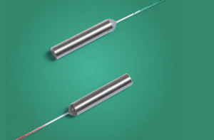
Essential Equipment Needed to Measure Faraday Mirror Rotation
Empirically measuring the rotation angle of optical components is a delicate procedure. You cannot accomplish this with standard optical power meters. It requires a specialized, highly calibrated test bench designed to isolate polarization states. Below is the critical equipment needed to execute this procedure accurately.
Stable Optical Light Source
The degree of rotation dictated by the Verdet constant of the magneto-optic crystal is intrinsically linked to the wavelength of the incoming light. Therefore, you must utilize a highly stable, narrow-linewidth laser source. This laser must perfectly match the designated operating wavelength of the device under test. Furthermore, experienced engineers know a crucial secret: power on the laser and allow at least 45 minutes for it to reach thermal equilibrium. This prevents subtle mode-hopping or wavelength drift that will inevitably skew your final calculations.
Polarization Controller and Polarimeter
To measure a shift in polarization, you must first establish a definitive starting point. A polarization controller is integrated into the setup to set the initial State of Polarization of the light before it enters the testing loop. This ensures a stable, known baseline.
The polarimeter serves as the analytical heart of this setup. It continuously reads the Stokes parameters of the light. Modern high-resolution polarimeters map these parameters visually onto a digital Poincaré sphere. This offers a real-time graphical representation of the light's behavior before and after reflection.
Optical Circulator or Coupler
Because the device under test operates by reflecting light back along the exact same physical path, you need a method to separate the returning signal from the input signal. A high-isolation 3-port optical circulator is the ideal tool for this task. Light originating from the laser enters Port 1 and is directed out of Port 2 into the mirror. The returning, rotated light re-enters Port 2 and is seamlessly routed out of Port 3 directly into the waiting polarimeter.
Step-by-Step Guide: How to Check the Rotation Angle
With the diagnostic bench properly assembled, you must adhere to a strict systematic procedure. This guarantees empirical accuracy and repeatability in the lab.
Step 1: System Calibration and Baseline Measurement
Before introducing the device into the network, calibrate the system to establish a reliable baseline. Route the thermally stabilized laser source through the polarization controller and directly into the polarimeter, bypassing the circulator for a moment. Manipulate the polarization controller to generate a distinct, easily identifiable State of Polarization on the Poincaré sphere. Record the exact Stokes parameters of this baseline. This represents your absolute zero-degree reference point.
Step 2: Integrating the Component into the Test Setup
Once the baseline is locked in, disconnect the direct line to the polarimeter and introduce the optical circulator into the architecture. Connect the laser to Port 1, the polarimeter to Port 3, and carefully splice or mate the device under test to Port 2.
In practice, physical cleanliness is paramount here. I cannot stress this enough: always inspect and meticulously clean all fiber optic connector end-faces using optical-grade lint-free wipes and isopropyl alcohol before mating. The satisfying click of a perfectly clean APC connector ensures that dirt or ambient oils will not induce localized insertion loss or polarization-dependent loss. Such contamination would instantly corrupt the polarimeter's readings.
Step 3: Capturing the Reflected Polarization State
Activate the full routing setup. The light travels through the circulator, enters the mirror, undergoes the dual-pass magnetic rotation, and travels back into the polarimeter. On the digital interface, you will watch the data point on the Poincaré sphere shift to a completely new location. Allow the reading to stabilize for several seconds. Ensure there are no environmental vibrations shaking the fiber leads, then document the output Stokes parameters.
Step 4: Calculating the Exact Rotation Angle
The final phase requires translating this raw optical data into a measurable physical angle. Calculate the angular difference between the input State of Polarization and the output state on the Poincaré sphere. Because the sphere maps angles at twice their physical value, a true 90-degree orthogonal physical rotation will appear as a 180-degree shift on the digital sphere. The input and output points should sit at exact opposite poles. If your calculated physical rotation lands between 89 degrees and 91 degrees, the device is functioning within acceptable industry tolerances.
Testing a PM Faraday Mirror vs. a Standard Faraday Mirror
What Makes a Polarization-Maintaining Component Unique?
While testing standard single-mode optical components is relatively straightforward, evaluating specialized PM variants introduces significant complexity. A PM Faraday mirror is engineered specifically for ultra-sensitive environments. In these setups, maintaining the Polarization Extinction Ratio is just as critical as the rotation angle itself. These advanced components utilize specialized fibers like PANDA or Bow-tie designs that feature strong internal stress rods. This intentional birefringence locks the light along a specific axis, preventing random drift caused by external mechanical stress.
Core Comparison: Standard vs. PM Testing Requirements
Feature / Requirement | Standard SM Faraday Mirror | PM Faraday Mirror |
|---|---|---|
Fiber Type | Standard Single-Mode | PANDA or Bow-Tie PM Fiber |
Primary Use Case | General telecom, basic interferometers | Fiber optic gyroscopes, coherent LiDAR |
Alignment Requirement | None specific, standard splicing | Strict alignment to Slow/Fast axis required |
Key Testing Metric 1 | 90° Round-Trip Rotation Angle | 90° Round-Trip Rotation Angle |
Key Testing Metric 2 | Insertion Loss < 0.6 dB | Polarization Extinction Ratio > 20 dB |
Specific Alignment and Testing Adjustments
When verifying a PM component, standard splicing techniques are entirely insufficient. The input light from the laser must be perfectly aligned with the slow axis of the PM fiber pigtail attached to the mirror. If the launch angle is misaligned by even a fraction of a degree, cross-coupling occurs. Light leaks into the opposing axis and rapidly degrades the polarization state before it ever reaches the magneto-optic crystal.
During this specialized testing, you must utilize a PER meter in conjunction with the polarimeter. The objective is twofold: confirm the round-trip rotation remains exactly 90 degrees, and verify that the Polarization Extinction Ratio remains exceptionally high. A sudden drop in PER during the test strongly indicates that the internal crystal is misaligned with the fiber axes. This renders the unit unfit for high-precision deployment.
Common Issues and Troubleshooting During Measurement
Even in highly controlled laboratory environments, empirical testing frequently yields anomalous readings. Before discarding a seemingly faulty component, systematically rule out these common environmental variables.
Temperature-Induced Angle Shifts
The Verdet constant of the internal magneto-optic crystal is inherently sensitive to thermal changes. As ambient laboratory temperatures rise or fall, the strength of the magnetic field interaction shifts. This directly alters the resulting rotation angle. If a component consistently tests at 86 degrees or 94 degrees, immediately check the room's climate controls. Testing should ideally be conducted in a stabilized environment around 23 degrees Celsius to establish an accurate performance baseline.
Wavelength Mismatch
Faraday rotation is fundamentally a function of wavelength. A component perfectly calibrated to provide a 45-degree single-pass rotation at 1550nm will yield a drastically incorrect angle if tested with a 1310nm or 1064nm laser source. Always cross-reference the component's specification sheet. Verify that your testing laser is tuned to the exact center wavelength of the device.
Mechanical Stress on the Fiber
Standard optical fibers are incredibly sensitive to physical manipulation. Bending the fiber pigtails too tightly, clamping them aggressively to the optical bench, or twisting them during the connection process induces artificial mechanical birefringence. This physical stress alters the polarization state before the light reaches the polarimeter, skewing the mathematical calculation of the angle. To prevent this, ensure all fiber leads are laid flat in gentle, wide loops that respect the manufacturer's minimum bend radius guidelines.
Buying Guide: How to Choose High-Quality Components
For procurement managers and optical network architects, the most cost-effective strategy for managing polarization issues is investing in premium components from the outset. This eliminates the constant need for reactive troubleshooting.
Key Specifications to Evaluate
When scrutinizing technical datasheets, look beyond the basic operating wavelength. Prioritize the following performance metrics to ensure long-term network stability:
Power Handling Capabilities: Match the component to your application. For standard sensing, a 300mW rating in the 1064-2050nm band is excellent. In contrast, heavy-duty industrial lasers require 20W high-power variants operating in the 780-1080nm range.
Rotation Angle Tolerance: High-precision units should guarantee a round-trip rotation of 90 degrees with a strict tolerance of ±1 degree or better.
Insertion Loss & Return Loss: Seek components with an Insertion Loss of less than 0.6 dB to preserve optical power. You also want a Return Loss greater than 50 dB to prevent destabilizing back-reflections into the laser source.
Polarization Extinction Ratio: For polarization-maintaining models, a minimum PER of 20 dB is non-negotiable to prevent cross-talk in coherent systems.
Partnering with a Reliable Manufacturer
Sourcing optical components from generic, unverified vendors frequently leads to high failure rates during internal quality control checks. It is highly recommended to partner with specialized optical manufacturers who supply factory-tested FRM Faraday Mirrors. Reputable manufacturers utilize automated alignment and laser-welding technologies to permanently secure the magneto-optic crystals. This ensures the rotation angle remains locked and environmentally stable throughout the entire lifespan of the device.
Conclusion
Accurately checking the rotation angle of a Faraday Mirror is not a trivial undertaking. It is a highly precise empirical process that demands the correct diagnostic tools, namely a stabilized laser source, a high-isolation circulator, and a high-resolution polarimeter. By mastering the mathematical relationship between Stokes parameters and the digital Poincaré sphere, you can confidently verify the performance of these indispensable components.
Whether you are constructing a standard telecommunications network using single-mode fiber or developing a highly sensitive interferometric sensor array requiring strict polarization maintenance, verifying that exact 90-degree orthogonal shift is the ultimate key. It neutralizes birefringence, minimizes signal fading, and eliminates optical noise. To safeguard the reliability of your optical infrastructure, prioritize components with rigorous angle tolerances and robust thermal stability. If you are looking to upgrade your optical test bench or deploy highly stable networks, explore the precision-engineered components at Kernstech to find the exact specifications your project demands.
FAQ
What is the standard rotation angle of a Faraday mirror?
The standard single-pass rotation angle is exactly 45 degrees. Because the optical signal travels through the magneto-optic crystal twice—once forward and once backward after reflecting off the rear mirror—the total round-trip rotation angle is precisely 90 degrees. This specific orthogonal shift is required to effectively cancel out accumulated birefringence in the fiber.
Can I manually adjust the rotation angle of a Faraday Mirror?
No, the rotation angle is entirely fixed during the manufacturing and assembly process. It is dictated by the specific magnetic field strength of the internal permanent magnet and the precise physical length of the magneto-optic crystal. If the angle proves to be incorrect during testing, the component cannot be recalibrated and must be completely replaced.
Why is my Faraday Mirror showing an angle of 85 degrees instead of 90?
This discrepancy usually occurs due to one of three common empirical reasons: testing the device with an incorrect laser wavelength, extreme ambient temperature fluctuations in the laboratory affecting the crystal's Verdet constant, or a fundamental manufacturing defect within the component itself. Always verify your test setup's calibration before discarding the unit.
What is the difference between a Faraday Rotator and a Faraday Mirror?
A Faraday Rotator is a transmissive, single-pass device that rotates the polarization of light as it passes continuously from one side to the other. Conversely, a Faraday Mirror combines a rotator with a reflective element, forcing the light to pass through the rotator twice. This results in a 90-degree total rotation, sending the compensated light back down the original input path.
Do I need a PM Faraday mirror for my setup?
You require a PM variant if your optical system utilizes PM fibers and demands strict preservation of the polarization extinction ratio. These specialized components are mandatory in highly sensitive applications such as fiber optic gyroscopes, advanced coherent communication systems, and interferometric sensors where polarization cross-talk cannot be tolerated.
How do you test the insertion loss of a Faraday mirror?
Testing insertion loss requires a stabilized light source and an optical power meter. First, measure the absolute output power of your light source to establish a reference. Next, connect the light source to Port 1 of an optical circulator, the Faraday Mirror to Port 2, and the power meter to Port 3. Subtract the circulator's known insertion loss from the final reading to isolate the true insertion loss of the mirror itself.
Does fiber bending affect the rotation angle measurement?
Yes, significantly. Bending or twisting the fiber leads induces mechanical stress, which creates artificial birefringence. This stress alters the state of polarization before the light reaches your measurement equipment, leading to inaccurate angle readings. Always lay the fiber flat in wide loops during testing to ensure the polarimeter is measuring the crystal's rotation, not the stress on the fiber jacket.


